Truss Alignment Tool
Jason Hedin
Senior Project
Design
Part 1: Defining the Parameters
The first step in the design process was to define the design requirements of the tool. In order to do this, a standard truss design was used, provided by the engineers at the Phoenix Truss Corporation.
A standard truss consisting of a 6:12 pitch, a 2x6 bottom chord, and 2x4 top chords was used to calculate the dimensions and output force needed by the tool. The required force was determined using the condition of a one inch offset at one end of a five foot section of truss. Any truss with a deflection more extreme than that would require replacement boards.

Part 2: Designing the Tool
The second step in the design process was to design the tool per the design requirements. The first part of this process was to make a preliminary design that would define how the tool would interact with each truss, as well as how each part would work together.
The dotted lines depict the centerline of each part, and represent the path through which the force is transmitted.
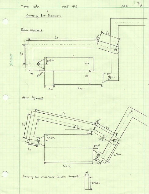
The input force needed on the tool was then calculated, and the design was modified until it met the design requirements

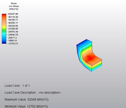
Part 3: Designing for Stress
The last step in the design process is to calculate the stresses in each part and modify the design to withstand the stresses present in each part.
AISI 1018 steel was used in every part, and has a yield strength of 68,000 psi.
The maximum stress in the connecting bar was calculated to be 53,880 psi, and an FEA model calculated this value to be 52,048 psi, resulting in an error of only 3.4%.